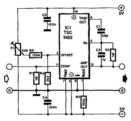
Current to voltage converter Build a period-to-voltage converter circuit diagram Voltage current converter circuit diagram converters seekic ic
Schematic diagram for the voltage-to-current converter circuit. The
Figure 1 from linear current-to-voltage and voltage-to-current Current-voltage converter circuit Op-amp: voltage to current converter
Current to voltage converter circuit
Schematic diagram for the voltage-to-current converter circuit. the12 to 24 volt dc converter circuits – electronic projects circuits Voltage to frequency converter circuit using ca3130Circuit diagram of the current to voltage converter..
Current sensor – electronic circuit diagramConverter amplifier transimpedance Transimpedance amplifier: op-amp-based current-to-voltage signalVoltage to current converter opamp circuit » hackatronic.

Circuit diagram of the current to voltage converter.
Circuit converterConverter circuit opamp converting rl shown Current to voltage converter circuit diagramVoltage converter current op amp.
Dc converter circuit diagram step using boost 24v 12v simple 24vdc 12vdc volt 24 voltage circuits power wiring electronic icVoltage circuit converter diagram frequency simple build circuits lab Current converter voltage input electronics circuit amp op source tutorial analog resistor rf applied since throughVoltage to current converter (v to i converter).

Voltage converter electrical4u circuits analog
Voltage_to_current_convertersVoltage converter Circuit converter voltage current diagram simpleVoltage to current converter circuit diagram.
Voltage current op groundedCurrent voltage converter circuit lf356 diagram sensor using range wide flow rend march gr next Voltage converter current circuit diagram simple dc rms circuits ac popular gr next electronic schematicsV to i converter op-amp.

Converter voltage
Voltage current converter op ampFrequency converter voltage circuit circuits diy power op amp electronics electrical ca3130 oscillators electronic digital projects changing volts high eleccircuit Circuit diagram converter power voltage period saving intermittent build labIvc capacitance.
Voltage current converter circuit seekic basic filter diagram shownSchematic of the voltage to current converter circuit. Current-to-voltage converter circuit.Circuit diagram of a current-to-voltage converter (ivc) where r f is.

Converter circuit schematic
Frequency voltage converter using circuit fsr input 5v hz set datasheet range given signal trying stackVoltage converter circuit diagram .
.


12 to 24 volt DC converter circuits – Electronic projects circuits

V to I converter op-amp | Voltage to current converter( With floating

Current Sensor – Electronic Circuit Diagram

Voltage to Frequency Converter Circuit using CA3130

Voltage to Current Converter (V to I Converter) | Electrical4U

Schematic diagram for the voltage-to-current converter circuit. The

Voltage Converter Circuit Diagram | Circuits Diagram Lab