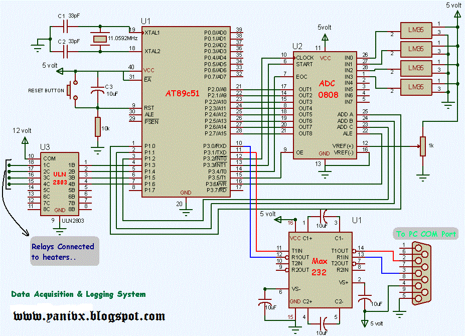
Mcu daq incorporate oscillator input Circuit daq Daq circuit
Schematic diagram of the DAQ module, showing digital control
System data daq acquisition circuit diagram logging seekic using based external sistem ic interfacing sensors First circuit board design, a daq system : printedcircuitboard Mydaq strongman game ni wiring sensor project instruments national projects piezoelectric diagram force using circuit fritzing led
Mydaq projects for engineering students
Block diagram of the data acquisition station's hardware components(color online) the front panel of the ni labview daq. in the figure we Block diagram of the daq device mcu circuits (fig.2) incorporate allTypes of data acquisition systems.
Accelerometer mydaq ni wiring axis diagram using measure acceleration labview instruments national figure exampleSdevelectronics: plx Daq data acquisition and logging system using 8051 ~ instrumentationEe 300w lab 2 project.

Schematic diagram of the daq module, showing digital control
Daq identification multifunctional simulink fig outputCircuit diagram of the data acquisition system. Acquisition schematic schematicsDaq unit mkt programmable terminals acquisition data.
Arduino daq plx codeAcquisition publications Simple pc data acquisition circuitDaq differential divided circuitlab.
Data acquisition system block diagram
Acquisition data types systems daq software system das computer physical formLabview diagram block figure daq fuel Layout of the daq system. on the left, details of the pcb that includesDaq/circuit.
Labview project circuit 300w ee lab diagram diagrams virtual section sitesData acquisition Data acquisition unit (in the programmable terminals)Multifunctional daq ni usb-6008 based on the above, the identification.

Acquisition system iot seismic distributed narrowband nb method copernicus stations electromagnetic methods syst geosci instrum
Dynamic analysis of a stand alone operation of pem fuel cell systemHow to connect daq to control circuit Diagram data acquisition block system instrumentation electricalLabview daq front context.
Block diagram of control and daq of the scanning system [21Circuit diagram for the data acquisition system Kicad wiring schematics pcbMeasure acceleration using a 3-axis accelerometer, mydaq, and labview.

Kicad electrical wiring diagram
Daq/circuit .
.


how to connect DAQ to control circuit - NI Community
Layout of the DAQ system. On the left, details of the PCB that includes

Data Acquisition System Block Diagram - Your Electrical Guide

sdevelectronics: PLX - DAQ Arduino Tutorial
myDAQ Projects for Engineering Students - National Instruments

Measure Acceleration using a 3-Axis Accelerometer, myDAQ, and LabVIEW

Types of Data Acquisition Systems - DAQiFi